Pad Printing Equipment
Pad Printing Equipment
Superior Repeatability Meets Unprecedented Efficiency

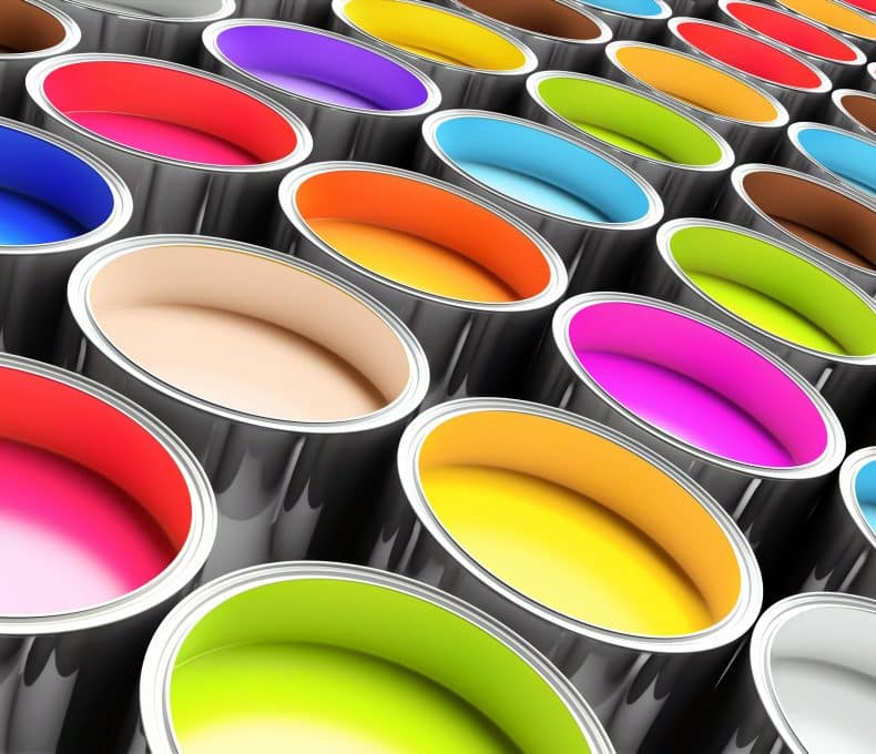
Trans Tech pad printing machines provide both single and multi-color product decoration. Our digital padprinters offer virtually limitless color options.
The experts in the Trans Tech Ink Lab can match your color requirements with market-leading precision. All color batches are kept to within a ΔE color variance of 2.0 or less.
In addition to providing a single image in two multiple colors, our pad printing equipment can print two separate images in two different places on a single part.
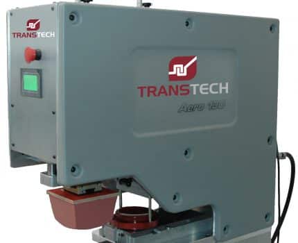
Trans Tech offers electromechanical, pneumatic and rotary pad print machines.
Electromechanical pad print machines provide streamlined and repeatable performance. Cam-driven movement is highly repeatable. Electromechanical machines are highly durable and maintenance-friendly.
Pneumatic systems are often favored for their cost-effectiveness as well as for their flexible pad stroke adjustment, which can accommodate parts of varying sizes. Pneumatic machines can also integrate a cup slide as an option—for printing on longer parts.
Rotary pad printing equipment is well-suited to printing cylindrical products at very high speeds.
Our technical experts can walk you through the benefits and considerations tied to each approach and help you find the best solution for your unique application.
For lower-volume applications that require greater flexibility- we offer stand-alone solutions fully compliant with OSHA safety standards. These systems allow for immediate manual visual part inspection.
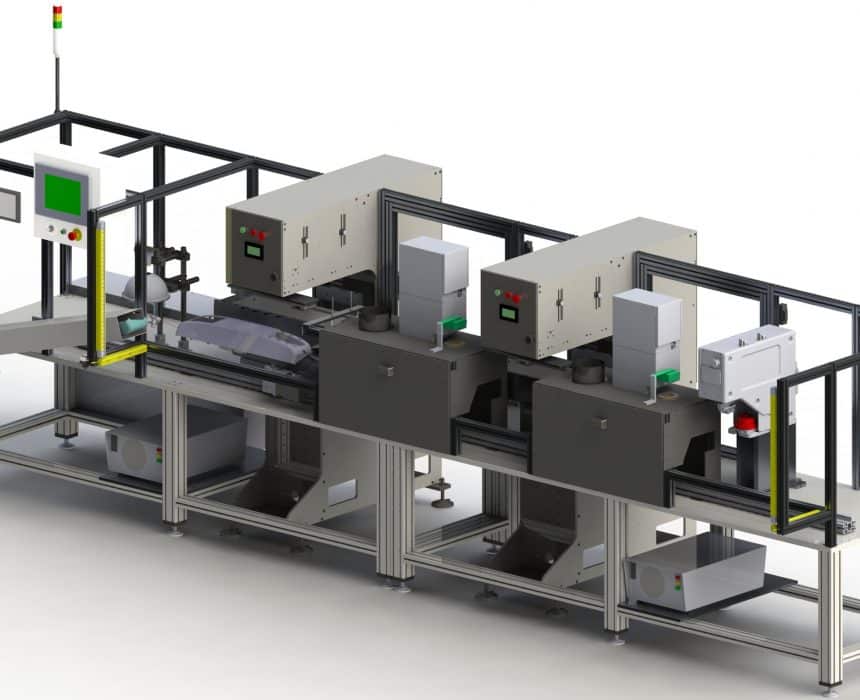
For higher volume applications, we provide semi- up to fully-automated systems that can incorporate elements like material handling and camera-driven quality control. In addition to providing superior reliability, these machines offer enhanced efficiency and reduced labor requirements.
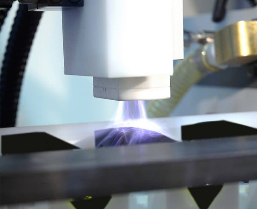
Both digital and pad printing provide highly durable print on a wide range of plastics , metal and wood substrates. Both techniques can be used to decorate treated and painted surfaces as well.
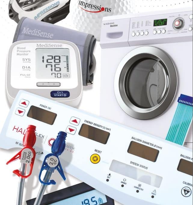
Pad printing machines are particularly well-suited to printing on a range of even the most challenging part geometries. Our printing equipment can decorate flat (linear), 2D, 3D, curved, recessed surfaces, and raised surfaces with the highest possible precision tolerances.
Pad Print Decoration
Benefits, Considerations, Trans Tech Expertise
Trans Tech has over 40 years of experience in designing and manufacturing pad printing equipment for product decoration. Our deep familiarity with the entire product decoration process allows to serve as a true One-Stop-Shop for pad printing needs. We provide pad printing machines as well as precision tooling, pads, plates and inks. Our systems run the gamut from manual to fully automated.